
Making & Fabrication
Print This Gauge Before Designing Anything That Has to Fit
There is no universal 3D-printing tolerance. One small clearance gauge can tell you what your printer, filament and settings will actually allow.
“Just add 0.2 mm” is not a law of physics
Ask how much clearance a 3D-printed part needs and somebody will confidently say 0.2 mm. Somebody else will say 0.3 mm. Then your lid will weld itself to the box and both of them will quietly leave the room.
There is no universal number. Printer calibration, material, orientation, geometry, layer height and first-layer squish all affect the result. Prusa suggests 0.3 mm as a reasonable starting point for moving parts on its machines, but it also says the correct value has to be tested.
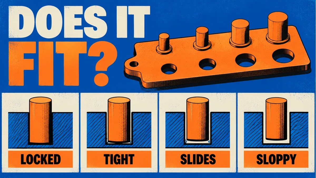
Download a free clearance gauge from Printables. The model presents several gaps in one compact print so you can feel which ones are locked, tight, sliding or loose on your setup.
Print it like a normal job
Do not use a magical ultra-slow profile that you never use anywhere else. Print the gauge with the machine, nozzle, material, layer height and profile you expect to use for the real project.
When it cools, test each labelled fit without attacking it with pliers. Record the smallest clearance that moves freely, the smallest that can be freed with gentle pressure and the one that feels right for a removable part.
The free gauge linked above is licensed CC BY-NC-SA. That makes it useful for personal calibration and sharing under the same terms with attribution, but it is not a commercial product file to resell.
The first layer may be the actual criminal
If the bottom edge is wider than the rest of the part, you may be seeing “elephant foot”: the first layer spreading under pressure. PrusaSlicer includes an elephant-foot compensation control, but changing it can affect thin details and brim contact.
Before redesigning an entire assembly, inspect the first layer. A peg that fits beautifully after the bottom half-millimetre may not have a clearance problem at all.
Try this first
Print one gauge in your normal PLA profile. Write the useful numbers directly on the spool label or material record. Print it again when you change material, nozzle, flow calibration or machine.
One small test will not make the printer perfect. It will stop you designing around a number borrowed from a stranger with different plastic, different settings and apparently supernatural confidence.